 |
|
Signalling |
|||||||||||
|
|
|||||||||||
|
Aspects of this section have been written by District Dave with contributions made by others, many of whom have a much deeper knowledge of the technicalities. As different lines have been upgraded so has signalling equipment, so, although all appearing broadly similar from where the Train Operator sits, the methods of control and operation varies. |
|||||||||||
 |
|
LONDON UNDERGROUND SIGNALLING by Roger Viggers The illustrations and captions were added by District Dave and appear in blue. Visitors to London acquainted mainline signalling practice doubtless find certain aspects of LUs signalling a touch confusing. Signals momentarily showing both red and green aspects or what appears to be a four aspect signal showing green and yellow are not what people brought up on the mainline are used to. The dual red/green aspect is caused by the associated trainstop arm being slow to drop when the signal goes to green. The section ahead being clear allows the proceed aspect to illuminate but the red stays lit until the trainstop is proved to be fully down. The trainstop arm is held up by springs and forced down by air pressure; some are a bit stiff and slow to move. A cause of trainstops failing to go down fully is rubbish, such as drink cans, becoming trapped underneath. |
|
|
|
||||||||||||||||||||||
|
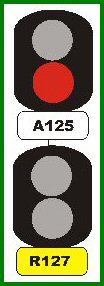
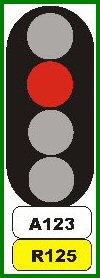
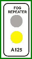
The apparent green and yellow is in reality two separate signals. The green is the proceed aspect of a stop signal while the yellow is the caution aspect of a repeater (not a distant). When the stop signal shows danger the repeater is completely extinguished. Repeaters are used where sighting distances are restricted and each one is for a designated signal. Sometimes a repeater is for more than one stop signal, but not always the next. To improve sighting in bad visibility additional repeaters are used. These are a miniature yellow/green signal with a white surround marked Fog Repeater. In multiple aspect area the yellow is replaced by a lunar white lamp with an F on the lens. In the diagrams the position of the signal plates is to highlight which relates to the signal and which to the repeater. In operation the plates are often mounted in the way illustrated for the four aspect version. In practice plates are not necessarily physically attached to the signals - there are many times where the plate is screwed to an adjacent wall or other piece of infrastructure - they are even found on the ground beneath a signal - particularly in covered areas such as tunnels where the signal head is of the tunnel type. |
|
|
|
|
|
|
 |
||||||||||||
|
London Underground does also use what appear to be 4 Aspect signals, but these are in fact two, two aspect signals but built onto the same mounting plate. They are identical in meaning to the examples above. Schematically they would look as follows: |
||||||||||||
 |
||||||||||||
|
Fog Repeaters appear on many parts of London Underground. In fact on the Sub Surface Lines (that is the District and Metropolitan) they are now left on at all times as part of London Undergrounds continued programme to drive down the number of SPADs that occur - these are often due to poor siting of signals and the signals in question of have no permanent repeater as described above. |
||||||||||||
|
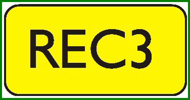
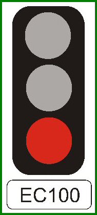
As on the mainline Automatic Signals are controlled by the passage of trains through track circuits. They normally show a green aspect until a train passes or a fault occurs. What on the mainline is called a controlled signal is on LU a Semi-Automatic Signal. The normal aspect is danger and it only clears when the signalman, or more likely a programme machine or computer, operates the control. As the train enters the section it automatically returns to red. Autos are used on plain track and Semis at junctions. Two types of signal number plates can be seen, black on white for stop signals and black on yellow for repeaters. Semi-automatic signals are numbers with a corresponding lever in the signal cabin or interlocking machine room (relay room) and are prefixed by the cabin code. Automatic signals are sequentially numbered and prefixed by the letter A. On part of the former City & South London Railway (Northern Line City Branch) the A is replaced by an S. |
|
|
|||||||||||||||||||||||||||||||||||||||||||||||||||||||||||||||||||||||


|
The layout of signals is similar to the absolute block system. The station, or junction, is the block post. At the front end of the platform is the Starter. If there is a junction just beyond the platform there may be Advance Starters on each branch. The signals approaching the station are the Home signals, of which there may be a number. At King's Cross on the eastbound Piccadilly Line there used to be five, the first two were speed controlled. Under speed controlled signaling if the driver had not reduced speed to a predetermined level the signal will remain at danger and if passed the train will be tripped resulting in an emergency brake application. As the train in the platform departs the home signals will clear in succession and the following train can enter. The whole system is designed to reduce headways and keep trains moving. |
|
|
|
||||||||||||||||||||||||||||
|
|
|
Route Indicators Route indicators are the familiar line of white lights at junctions, Junction Route Indicators known as Harbour Lights. For shunting moves to two or more routes a matrix of individual lamps called a Theatre Route Indicator is used. When a move is set up 1 is used for the leftmost route, 2 for the second from left and so on. |
|
|
|
||||||||||||||||||||||
|
|

|
Peculiar LU Signals There are signals peculiar to LU. Two of these are X signals and Draw-up signals. The first of these is sited before special items such as floodgates and as the first signal after a Surface Stock Detector. This is a device sited on the approach to a tube stock loading gauge tunnel where surface stock might inadvertently gain access, such as the Piccadilly Line tunnel mouth at Barons Court. They consist of a gantry with three U shaped mercury filled glass tubes suspended. If a surface stock train tries to pass the tubes will be broken and the signal will remain at danger. Draw-up signals are miniature speed controlled three-aspect signals sited partway along platforms where there is a converging junction just ahead of the platform starter. When the route is set for a train to join the track in question an approaching train has to reduce speed to a predetermined level when the draw-up signal will clear to a yellow. The incoming train can then continue to the stopping mark. |
|
|
|
||||||||||||||||||||||||||||||||||||||||||||


|
Following the Moorgate incident in 1975 special measures were introduced at terminal stations. Firstly trains have their speed reduced by speed control signals on the approach. The traction current supply is the restricted to prevent the driver applying power to the motors. When entry to the platform is on an up grade limited current is available to overcome its effects. Sited along the Platform are Policemen. These are trainstops without a signal and unless the train continues to reduce speed will remain raised and operate the trainstop operating the train. Traction current rail gaps are marked by special signals which only illuminate when the current is off in the section ahead. Rail Gap Indicators consist of three red lights in a white triangular plate marked as such. Their repeaters are similar but both lights and plates are yellow. Signaling on both the Victoria and Central Lines is different as they are equipped for Automatic Train Operation. Chiltern Railway class 165s permitted to operate over LU metals and those mainline stocks operating in single track tube tunnels are also fitted with tripcocks. |